Altair Floppy Disk (88-DCDD)
Altair floppy disk (88-DCDD) offered the advantage of permanent store including relatively fast access to data. The speed of data transfer was 250 Kbit/s (The plugin does not emulate this). Data transfer was serial, byte after byte.
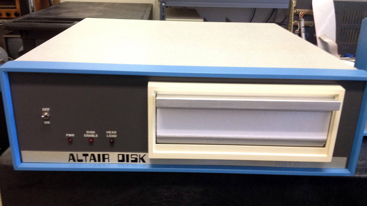
(The image was borrowed from deramp.com).
The 88-DCDD hardware contained three parts:
- disk drive (initially Pertec FD400), able to store ~330 kB of data on 8” diskette
- two boards connected to S-100 bus
- the first one performed communication operations between the bus and CPU
- the second one performed communication with the disk drives
Original manual can be found at deramp.com or www.virtualaltair.com.
Diskette formats
A diskette was introduced by IBM in 1971 for being able to load programs into IBM mainframes. Soon a revolution in personal computers brought diskettes into the world of microcomputers.
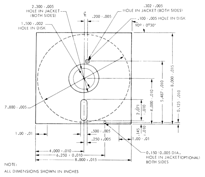
Standard Altair 8” diskette had the following parameters:
| Description | Value |
|---|---|
| Maximum capacity | 330 kB |
| Recording density | 6331 bits per radian (3268 bits per inch) |
| Tracks | 77 |
| Sectors per track | 32 |
| Sector size | 137 bytes |
(info from Pertec FD400 manual, this blogpost and simh emulator)
Features of the plugin
The 88-dcdd plugin emulates basic functionality of the whole disk system for Altair 8800 computer. It is not only disk controller, but also includes 16 disk drives.
Feature highlights are:
- Up to 16 disk images can be mounted, optionally mounted automatically on startup
- CPU ports can be set manually
- GUI showing disk activity in runtime
- Interrupts are supported
GUI can be seen in the following image:
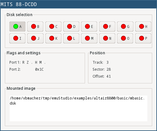
The window shows runtime status of virtual disk drives. By clicking on a drive button, its details are revealed below. Port1 is showing 88-dcdd status, ordered from the MSB to LSB, and instead of showing 1 and 0s, every bit is mapped to a letter:
R(bit 7): “New read data” available - indicates that one byte of data is available to be read from port 2Z(bit 6): Indicates when head is on outermost track (track 0)I(bit 5): Indicates interrupts enabled (value=0) or disabled (value=1)H(bit 2): Head status (loaded: value=0, unloaded: value=1)M(bit 1): Indicates head movement allowed (allowed: value=0, disallowed: value=1)W(bit 0): “Enter new write data” - indicates new byte of data can be written to port 2
You might notice on “true” condition the bit value of Port 1 is 0. Also, the drive button icon color reflects the head status: green means head is loaded, red means head is unloaded. See 88-dcdd manual for more details.
Mounting disk images
In order to mount disk images to the device, please open device settings:
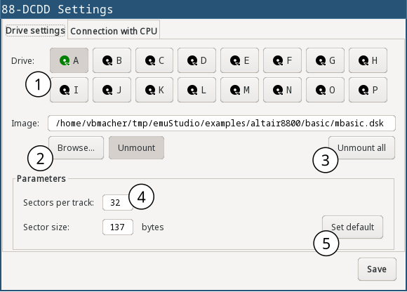
| 1 | Select drive (A - P) |
| 2 | Choose the image file and click on “Mount”. If there is a disk mounted already, it will be re-mounted with the new file. |
| 3 | If you want to un-mount all disk drives, click on “Umount all” button |
| 4 | Set sectors per track and sector size for the current drive. (NOTE: Be cautious with the settings. Incorrect values can result in disk image file damage. Existing default values were chosen from disk image files used by simh emulator). |
| 5 | Set default values for sectors per track and sector size for the current drive. |
CPU Ports settings
A control board of Altair disk communicates with CPU through its ports. There are three ports overall, each for different function. By default, the port mapping to CPU port numbers is as follows:
- Port 1:
0x08- in: disk status information, out: select disk - Port 2:
0x09- in: get number of sector, out: disk settings - Port 3:
0x0A- in: read data, out: write data
Port mapping can be changed in the Settings window, tab “CPU Ports”:
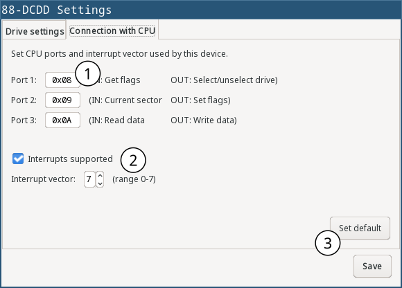
| 1 | Set CPU port number value for the three 88-dcdd ports |
| 2 | Set used CPU interrupt vector and whether interrupts are actually supported by 88-dcdd. Interrupt vector is used when interrupt is signalled to the CPU which is implemented as equivalent to executing an instruction RST. When interrupts are globally disabled here, enabling them in runtime won’t work. |
| 3 | Setting default interrupt vector (which is 7) |
Programming
The basic idea is to programmatically select a drive, then set a “position”. After that data can be either read or written. For nice introduction with historical context see this nice blog post.
The “position” in the floppy disk is determined by a track number, sector number and the offset within the sector. It is rudimentary to know how many tracks are available, so as how many sectors per track and the sector size.
In Altair8800, drive Pertec FD400 used 8” diskettes. Each had 77 tracks. A track had 32 sectors with 137 bytes long. The capacity of a diskette was therefore 77 * 32 * 137 = 337568 B = 330 kB. Software used less capacity, because 9 bytes of each sector were used for the integrity checksum.
Setting the position
In the original device, the position was changing automatically by the diskette rotation inside the disk drive. Since CPU was much faster than a rotation, the idea was to probe the current drive position (track and sector number) from the CPU and when the position matched the requested one, data could be read or written.
emuStudio plugin does this in a more predictable way. Instead of automatic changing the position asynchronously, it is changed in time when a programmer actually performs the probing. For example, to set the sector number to - say - 5, the programmer must probe the sector 5 times.
Setting the offset within a sector is more challenging. After the track and sector are set, programmer must - again - probe the status port telling if current disk position is actually set at the beginning of the sector. If so, then a programmer must read the data until which increments the position, until the position is as requested.
CPU Ports
In the real world, two controller boards communicated with CPU using three I/O ports. The plugin utilizes the ports the same way as the real device. The following table shows the CPU ports and how they are used.
| Port | Address | Input | Output |
|---|---|---|---|
| 1 | 0x08 | Disk and controller status | Select disk |
| 2 | 0x09 | Get number of sector | Disk settings |
| 3 | 0x0A | Read data | Write data |
Now, detailed description of the ports follow. Bits are ordered in a byte as follows:
D7 D6 D5 D4 D3 D2 D1 D0
where D7 is the most significant bit, and D0 the least significant bit.
Port 1 (default address: 0x08)
WRITE:
Selects and enables one of 16 disk devices. By selecting a drive, all further operations will be performed on that drive. If the disk has not mounted any disk image, all further operations will be ignored. The previously selected device will be disabled.
D7: if the value is 1, disable the drive. If the value is 0, select and enable the drive.D6 D5 D4: unused bitsD3 D2 D1 D0: index of the drive to be selected. From 0-15.
READ:
Read disk status of the selected drive.
D7: New read data available. Indicates if there is at least 1 byte available for reading from Port 3 (value=0). It will be reset after data are read (value=1). If the value is 1, data read from Port 3 will be invalid or no new data is available.D6: Track 0. Indicates if the head is positioned at track 0 (value=0).D5: Interrupt Enabled. Indicates if interrupts are used (value=0).D4 D3: Unused bits; they are always 0.D2: Head Status. Indicates the correctness of the head setting. If the value is 0, reading sector number from Port 2 will be valid.D1: Move head. Indicates if the movement of the disk head is allowed. If the value is 1, all track number changes will be ignored.D0: Enter new write data. Indicates if the device is ready for writing data. If the value is 1, all written data will be ignored.
Initial values of the bits are: 11100111.
Port 2 (default address: 0x09)
WRITE:
Control the disk head, and other settings if a disk drive is selected.
D7: Write Enable. Initializes write sequence (enables writing to the disk; value=1). The plugin sets the sector number to 0 and also value 0 to bitD0of Port 1 (Enter new write data). According to the manual, a writing sequence holds only for short time, maximally until the end of sector is reached. The plugin does not limit the sequence period, it is deactivated only when the end of the sector is reached. In addition, each first byte and the last byte of a sector should have set its MSB (7th bit) to 1. It was called the “sync bit” for easier identification of start or end of a sector. However, the plugin does not require it.D7: Write Enable. Initializes write sequence (enables writing to the disk; value=1). The plugin sets the sector number to 0 and also value 0 to bitD0of Port 1 (Enter new write data). According to the manual, a writing sequence holds only for short time, maximally until the end of sector is reached. The plugin does not limit the sequence period, it is deactivated only when the end of the sector is reached. In addition, each first byte and the last byte of a sector should have set its MSB (7th bit) to 1. It was called the “sync bit” for easier identification of start or end of a sector. However, the plugin does not require it.D6: Head Current Switch. On real disks the bit should be set to 1 when a program is writing data to tracks from 43-76. The plugin the bit is ignored.D5: Interrupt Disable. If set to 1, interrupts support will be disabled.D4: Interrupt Enable. If set to 1, interrupts support will be enabled. Interrupt will be signalled to CPU on “sector true” event. This effectively means on every other position reading (see READ part below). The device will emit interrupt vector equivalent to executing anRSTinstruction. The interrupt vector number is set up globally
in the plugin settings.D3: Head unload. Removes head from the disk surface. Reading sector number will now become invalid. In addition, value of bitD7from Port 1 (New read data available) become 1 (no new data).D2: Head load. Sets the disk head onto disk surface. Reading sector number now becomes valid. If additionally the bitD7from Port 1 (New data available) is set, it is possible to read data from the disk.D1: Step Out. Move the disk head back by 1 track (the track number is decremented). It is required to check bitD1of Port 1 (Move head) to have value 0.D0: Step In. Move the disk head ahead by 1 track (the track number is incremented). It is required to check bitD1of Port 1 (Move head) to have value 0.
READ:
Reads the number of the sector. The value can be read only if a disk drive is selected and the disk head is positioned at the disk surface (by setting the bit D2).
D7 D6: Unused bits; they are always 1.D5 D4 D3 D2 D1: Number of the sector, counted from 0.D0: Sector True. If the value is 0, the offset in sector is 0. According to manual, the bit is set for maximum 30 microseconds. Programs could detect the bit set and quickly start writing data until the Sector true came back again. It could be made in time easily, because CPU was much faster than disk itself. plugin does not limit the period. The value is 0 practically all the time, until first byte is written.
Port 3 (default address: 0x0A)
WRITE:
Write a byte to disk. In order to perform valid write, the Write Enable D7 bit of Port 2 must be set to 1. Before data are written to disk, it is required to check bit D0 from Port 1 (Enter new write data).
READ:
Read a byte from disk. In order to perform valid read, the Head load D2 bit of Port 2 must be set to 1. Only if bit D7 from Port 1 (New read data available) is set to 0, the read data are valid.
Program example
In this section, an example is presented showing how to read/write data from/to the floppy disk. At first, it writes one byte (letter A with ASCII value 65) to track 1, sector 18 and offset 20. Then, it reads the byte to operating memory at address 0x200.
The program uses 3 procedures (in assembler for Intel 8080) for setting the disk position (ltrack for loading the track number, lsector for loading the sector number, and loffset for loading the offset within the sector) and two more for data reading (read) and writing (write).
disk0  equ 0    ; disk number
track  equ 1    ; track number
sector equ 18   ; sector number
offset equ 20   ; offset within the sector
data   equ 'A'  ; data for writing

dcx sp          ; set stack register to 0xFFFF

mvi a, disk0    ; select disk
out 08h

call ltrack     ; set track number

call we         ; set 'write enable' sequence
call lsector    ; set sector number
call loffset    ; set sector offset
call write      ; write data

call lsector    ; set sector number (for clearing the offset)
call loffset    ; set sector offset
call read       ; read data

lxi h, readdata ; load address for reading the data
mov m, a        ; move the data there

hlt             ; end

ltrack0:        ; the procedure will set track number to 0
in 08h          ; read disk status
ani 1000000b    ; track 0 ?
rz              ; yes, return
mvi a, 1000b    ; head unload
out 09h
call movetrk    ; wait until the disk head can be moved
mvi a, 10b      ; step out, decrement track number
out 08h
jmp ltrack0

ltrack:         ; procedure sets a track number
call ltrack0    ; at first, set track number to 0
mvi b, track+1  ; b = track + 1
stepin:         ; stepin: {
dcr b           ;   b--;
rz              ;   if (b == 0) return;
call movetrk    ;   wait until the disk head can be moved
mvi a, 1        ;   step in, increment track number
out 09h
jmp stepin      ;   goto stepin;
                ; }

movetrk:        ; procedure waits until the disk head can be moved
in 08h          ; read disk status
ani 10b         ; can the disk head be moved?
jnz movetrk     ; nope, try again...
ret             ; yes, return

lsector:        ; procedure sets a sector number
mvi a, 100b     ; head load
out 09h
waits:
in 09h          ; read sector number
ani 3Fh         ; clear unused bits
rrc
cpi sector      ; is the number what is requested?
jnz waits       ; nope, try again
ret             ; yes, return

loffset:        ; procedure sets a sector offset
mvi b, offset+1 ; b = offset + 1
stepoff:        ; stepoff: {
dcr b           ;   b--;
rz              ;   if (b == 0) return;
call read       ;   read data; the offset is incremented
jmp stepoff     ;   goto stepoff;
                ; }

read:           ; procedure reads data from the disk
in 08h          ; read disk status
ani 100b        ; check if the disk head is loaded on the disk surface
rnz             ; if not, return
waitr:
in 08h          ; read disk status
ani 10000000b   ; New read data available ?
jnz waitr       ; nope, try again...
in 0Ah          ; yes, read data
ret             ; return

we:             ; procedure enables 'write enable' sequence
mvi a, 10000000b ; write enable
out 09h
ret

write:          ; procedure writes data to the disk
in 08h          ; read disk status
ani 100b        ; check if the disk head is loaded on the disk surface
rnz             ; if not, return
waitw:
in 08h          ; read disk status
ani 1           ; enter new write data ?
jnz waitw       ; nope, try again...
mvi a, data     ; yes, write data
out 0Ah
ret

org 200h
readdata: db 0
Experimental CP/M support
88-dcdd plugin adds highly experimental support of handling files on a CP/M filesystem. It is now possible to create disk images, and read/write files from/to a disk image using CP/M filesystem.
The CP/M tool can be accessed from command-line:
> bin/88-dcdd --help

Usage: 88-dcdd [-hV] [-F=FILE] (-l | (-f=FORMAT -i=FILE)) [COMMAND]
88-DCDD Altair floppy disk drive
  -f, --format=FORMAT      disk format ID
  -F, --format-file=FILE   disk format file (TOML)
  -h, --help               Show this help message and exit.
  -i, --image=FILE         disk image file
  -l, --list-formats       lists available disk format IDs
  -V, --version            Print version information and exit.
Commands:
  cpmfs, cpm  CP/M filesystem commands
In order to be able to work with a disk image, the tool needs to know disk image format. The disk format is selected using -f argument, followed by format ID.
Example files reading/writing
In order to work with a disk image the image file and disk format must be selected, followed by a CP/M command:
> bin/88-dcdd -i altcpm.dsk -f cpm2-simh cpm

Missing required subcommand
Usage: 88-dcdd cpmfs [-hV] [COMMAND]
CP/M filesystem commands
  -h, --help      Show this help message and exit.
  -V, --version   Print version information and exit.
Commands:
  cat         Show file content
  copy, cp    Copy files
  dates       Show files dates
  format      Format CP/M disk image
  info        Volume information
  list, ls    List files
  remove, rm  Remove file
Now you can see all the options of the CP/M tool. Let’s list all the files in the disk image:
> bin/88-dcdd -i altcpm.dsk -f cpm2-simh cpm ls

St |File name    |Flags   |Ex |S2 |Rc |Bc |Al
---------------------------------------------
00 |    STAT.COM |        |00 |00 |2a |00 |08 09 0A 0B 0C 0D 00 00 00 00 00 00 00 00 00 00
00 |     PIP.COM |        |00 |00 |3a |00 |0E 0F 10 11 12 13 14 15 00 00 00 00 00 00 00 00
00 |      ED.COM |        |00 |00 |34 |00 |16 17 18 19 1A 1B 1C 00 00 00 00 00 00 00 00 00
00 |     DDT.COM |        |00 |00 |26 |00 |1D 1E 1F 20 21 00 00 00 00 00 00 00 00 00 00 00
00 |     ASM.COM |        |00 |00 |40 |00 |22 23 24 25 26 27 28 29 00 00 00 00 00 00 00 00
00 |    LOAD.COM |        |00 |00 |0e |00 |2A 2B 00 00 00 00 00 00 00 00 00 00 00 00 00 00
00 |  SUBMIT.COM |        |00 |00 |10 |00 |2C 2D 00 00 00 00 00 00 00 00 00 00 00 00 00 00
00 |    XSUB.COM |        |00 |00 |06 |00 |2E 00 00 00 00 00 00 00 00 00 00 00 00 00 00 00
00 |  MOVCPM.COM |        |00 |00 |60 |00 |2F 30 31 32 33 34 35 36 37 38 39 3A 00 00 00 00
00 |    COPY.COM |        |00 |00 |06 |00 |3B 00 00 00 00 00 00 00 00 00 00 00 00 00 00 00
00 |  FORMAT.COM |        |00 |00 |0e |00 |3C 3D 00 00 00 00 00 00 00 00 00 00 00 00 00 00
00 |    DUMP.COM |        |00 |00 |03 |00 |3E 00 00 00 00 00 00 00 00 00 00 00 00 00 00 00
00 |  SYSGEN.SUB |        |00 |00 |02 |00 |3F 00 00 00 00 00 00 00 00 00 00 00 00 00 00 00
00 |    DUMP.ASM |        |00 |00 |26 |00 |45 46 47 48 49 00 00 00 00 00 00 00 00 00 00 00
00 |     PTD.HEX |        |00 |00 |06 |00 |4A 00 00 00 00 00 00 00 00 00 00 00 00 00 00 00
00 | ABOOT62.HEX |        |00 |00 |01 |00 |4B 00 00 00 00 00 00 00 00 00 00 00 00 00 00 00
00 |   CBIOS.HEX |        |00 |00 |16 |00 |4C 4D 4E 00 00 00 00 00 00 00 00 00 00 00 00 00
00 |   CBIOS.ASM |        |00 |00 |3d |00 |61 62 63 6D 6E 72 73 74 00 00 00 00 00 00 00 00
00 |     PTD.ASM |        |00 |00 |0e |00 |5F 60 00 00 00 00 00 00 00 00 00 00 00 00 00 00
00 |      LS.COM |        |00 |00 |18 |00 |40 41 42 00 00 00 00 00 00 00 00 00 00 00 00 00
00 |   CPM62.COM |        |00 |00 |48 |00 |64 65 66 67 68 69 6A 6B 6C 00 00 00 00 00 00 00
00 |  SURVEY.COM |        |00 |00 |0a |00 |50 51 00 00 00 00 00 00 00 00 00 00 00 00 00 00
00 | ABOOT62.ASM |        |00 |00 |04 |00 |86 00 00 00 00 00 00 00 00 00 00 00 00 00 00 00
In order to copy a file to host filesystem, it is possible to use copy subcommand, but for outputting it on screen let’s use cat:
> bin/88-dcdd -i altcpm.dsk -f cpm2-simh cpm cat CBIOS.ASM

; ALTAIR 8800 BIOS WITH 8800 DISK DRIVES - 256 FILES EACH
;
MSIZE   EQU     62              ;MEMORY SIZE
BIAS    EQU     (MSIZE-20)*1024
CCP     EQU     3400H+BIAS      ;START OF CCP
BDOS    EQU     CCP+806H
BIOS    EQU     CCP+1600H

        ORG     BIOS

NSECTS  EQU     ($-CCP)/128     ;# SECTORS TO BOOT
LADDR   EQU     CCP+(51*128)
PART2   EQU     CCP+(27*128)
IOBYTE  EQU     3
CDISK   EQU     4
...
In order to write a file to a disk image, let’s prepare one, name it test on a host filesystem:
Testing, testing!
In order to copy the file on the disk image, let’s use the already mentioned copy command:
> bin/88-dcdd -i altcpm.dsk -f cpm2-simh cpm cp --help

Copy files
Usage: 88-dcdd cpmfs copy [-hV] SRC_FILE DST_FILE
Copy a file between CP/M disk image and host
      SRC_FILE    source file (cpm:// prefix if in CP/M disk image)
      DST_FILE    destination file (cpm:// prefix if in CP/M disk image
  -h, --help      Show this help message and exit.
  -V, --version   Print version information and exit.
So we know the destination is the disk image, thus the copy command would be:
> bin/88-dcdd -i altcpm.dsk -f cpm2-simh cpm cp test cpm://test
And now “test” it:
> bin/88-dcdd -i altcpm.dsk -f cpm2-simh cpm cat test
Testing, testing!
Disk formats
Various disk file formats are stored in a file, by default located in examples/altair8800/cpm-formats.toml (possible to change location with -F argument). Example disk format for CP/M 2.2 and standard Altair 8” diskette:
# Altair 8" floppy disks for SIMH CP/M 2.2
#
# altcpm.dsk    http://cpmarchives.classiccmp.org/cpm/mirrors/www.schorn.ch/cpm/zip/altsw.zip
[[format]]
id = 'cpm2-simh'
sectorSize = 137
sectorSkew = 17
sectorOps = 'altair-floppy-mits'
bcInterpretsAsUnused = false
dateFormat = 'NOT_USED'

[format.dpb]
driveSpt = 32
spt = 32
bsh = 3
# or blm = 7
dsm = 254
drm = 255
al0 = 0xFF
al1 = 0
ofs = 6
The diskette format contains two sections: [[format]], which is the main (root) section, and [format.dpb] which is a subsection with disk-parameters-block (DPB).
The main section supports the following parameters:
| Name | Default value | Valid values | Description |
|---|---|---|---|
id | any string without spaces | Disk format ID | |
sectorSize | > 0 | Raw sector size in bytes | |
sectorSkew | 1 | optional; > 0 | Sector skew in bytes. It is not required to provide, if a sector skew table is provided. Used if sectorSkewTable is not provided. |
sectorSkewTable | optional; array of sectors-per-track items (see driveSpt below) | Sector skew table. Used if sectorSkew is not provided. | |
sectorOps | dummy | altair-floppy-mits, altair-floppy-deramp, altair-minidisk-deramp, dummy | Sector operations - how to extract data from raw sector when reading, or how to encode data to raw sector when writing. See below for more information. |
bcInterpretsAsUnused | false | true/false | BC is a value in a CP/M file record saying number of used bytes in the last data record for the file (false) or number of unused bytes in the record (true). |
dateFormat | NOT_USED | NOT_USED, NATIVE, NATIVE2, DATE_STAMPER | What type of date format this CP/M filesystem uses. See a description below. |
sectorsPerTrack0 … sectorsPerTrack15 | 32 | > 0 | Count of sectors in a disk image, on disk A (0) up to P (15) |
sectorSize0 … sectorSize15 | 137 | > 0 | Size of one sector in bytes on disk A (0) up to P (15) |
image0 … image15 | N/A | Path to existing file | File name to mount on disk A (0) up to P (15) |
imageMounted0 … imageMounted15 | false | true/false | Whether disk image is mounted on start |
interruptVector | 7 | 0 to 7 | Interrupt vector to be used when an interrupt is signalled to CPU |
interruptsSupported | true | true/false | Whether interrupts are supported (independent on Port 2 runtime settings) |
Sector operations (sectorOps)
In CP/M, data records are usually prefixed and/or appended with additional data like checksum in order to obtain full sector. A CP/M data record has 128 bytes (this is fixed for all CP/M versions). But standard Altair 8” diskette had capacity of 137 bytes, thus still having available space of 9 bytes.
On reading, these data/checksums were usually checked before the data is extracted. Various CP/M versions used different sector operations - meaning data records might be placed on various different positions (different offsets) in the raw sector.
This section will describe sector operations supported in 88-dcdd CP/M tool. There are more possibilities of sector arrangement, but currently only the following are supported.
Dummy
Value: dummy
Record is not manipulated at all. Sector size is respected, so the 128-byte record is placed in the beginning of the sector, padding the rest of available sector space with 0.
Altair Floppy: MITS
Value: altair-floppy-mits
This sector ops are used in simh Altair8800 disk images, assuming standard 8” Altair diskette. Here the sector size is hardcoded to 137 bytes, regardless of what is in the settings. The sector is arranged as follows:
| Byte | Description |
|---|---|
| 0 | Track number + 0x80 |
| 1 | Skewed sector = (Sector number * 17) MOD 32 (the sectorSkew from the settings is overriden to 17, driveSpt overriden to 32) |
| 2 | 0 |
| 3 - 131 | Data |
| 132 | 0xFF (“stop byte”) |
| 133 | Data checksum (sum of bytes 3-131) |
| 134 | 0 |
| 135 | 0 |
| 136 | 0 |
Altair Floppy: DeRamp
Value: altair-floppy-deramp
This sector ops is described in DeRamp CP/M BIOS, assuming standard 8” Altair diskette. The sector size is hardcoded to 137 bytes, regardless of what is in the settings.
The sector arrangement is different based on a track number. For tracks 0-5, the arrangement is:
| Byte | Description |
|---|---|
| 0 | 0 |
| 1 | 1 |
| 2 - 130 | Data |
| 131 | 0xFF (“stop byte”) |
| 132 | Data checksum (sum of bytes 2-130) |
| 133 | 0 |
| 134 | 0 |
| 135 | 0 |
| 136 | 0 |
For tracks 5-76, the arrangement is:
| Byte | Description |
|---|---|
| 0 | Sector number (not skewed) |
| 1 | 0 |
| 2 | 0 |
| 3 | 0 |
| 4 | 0 |
| 5 | 0 |
| 6 - 134 | Data |
| 135 | 0xFF (“stop byte”) |
| 136 | data checksum (sum of bytes 6-134) |
Altair Minidisk: DeRamp
Value: altair-minidisk-deramp
This sector ops is described in DeRamp CP/M BIOS, assuming 5.25” Altair Minidisk. The sector size is hardcoded to 137 bytes, regardless of what is in the settings.
The sector arrangement is different based on a track number. For tracks 0-3, the arrangement is:
| Byte | Description |
|---|---|
| 0 | 0 |
| 1 | 1 |
| 2 - 130 | Data |
| 131 | 0xFF (“stop byte”) |
| 132 | Data checksum (sum of bytes 2-130) |
| 133 | 0 |
| 134 | 0 |
| 135 | 0 |
| 136 | 0 |
For tracks 4-34, the arrangement is:
| Byte | Description |
|---|---|
| 0 | Sector number (not skewed) |
| 1 | 0 |
| 2 | 0 |
| 3 | 0 |
| 4 | 0 |
| 5 | 0 |
| 6 - 134 | Data |
| 135 | 0xFF (“stop byte”) |
| 136 | data checksum (sum of bytes 6-134) |
Date formats (dateFormat)
Date formats are partially described in various manuals: CP/M tools manual, BDOS replacements for CP/M 2 and 3, CP/M 2.2 file format, CP/M 3.1 file format and CP/M 4.1 file format.
Naive 1
Value: NATIVE
Used in CP/M 2.2 in various BDOS replacements: Z80DOS, DOS+, P2DOS and CP/M Plus. Every 4th entry of a directory is considered to be a datestamp record. The structure of the record is as follows:
21 00 C1 C1 M1 M1 M1 M1 A1 A1 A1 A1 C2 C2 M2 M2
M2 M2 A2 A2 A2 A2 C3 C3 M3 M3 M3 M3 A3 A3 A3 A3
C1= File 1 Create dateM1= File 1 Modify date/timeA1= File 1 Access date/timeC2= File 2 Create dateM2= File 2 Modify date/timeA2= File 2 Access date/timeC3= File 3 Create dateM3= File 3 Modify date/timeA3= File 3 Access date/time
Native 2
Value: NATIVE2
This file format is described only on single place (here) and Im not sure if it really existed. If yes, it’s possible to use it. The source claims the format was used in P2DOS or CP/M Plus BDOSes. Every 4th entry of a directory is considered to be a datestamp record. The structure is as follows:
21 C1 C1 C1 C1 M1 M1 M1 M1 00 00 C2 C2 C2 C2 M2
M2 M2 M2 00 00 C3 C3 C3 C3 M3 M3 M3 M3 00 00 00
C1= File 1 Create dateM1= File 1 Modify date/timeC2= File 2 Create dateM2= File 2 Modify date/timeC3= File 3 Create dateM3= File 3 Modify date/time
The source further says: CP/M Plus further allows optionally to record the access instead of creation date as first time stamp.
- 2 bytes (little-endian) days starting with 1 at 01-01-1978
- 1 byte hour in BCD format
- 1 byte minute in BCD format
This is however not supported in this date format.
Date stamper
Value: DATE_STAMPER
File date/times are saved in a special file called !!!TIME&.DAT in the CP/M filesystem. The file during CP/M runtime is managed by the special software called DateStamper, which must be installed to BDOS manually ( described here, here and here).
88-dcdd CP/M tool does not support this type of date formats for now. Since the file !!!TIME&.DAT has special requirements (it must be allocated as the first record in directory entry), the setting DATE_STAMPER only makes sure the first directory is ignored during entry allocation when writing files to disk image.
Configuration file
The following table shows all the possible file configurations of the plugin:
| Name | Default value | Valid values | Description |
|---|---|---|---|
port1CPU | 0x08 | > 0 and < 256 | Number of Port 1 |
port2CPU | 0x09 | > 0 and < 256 | Number of Port 2 |
port3CPU | 0x0A | > 0 and < 256 | Number of Port 3 |
sectorsPerTrack0 … sectorsPerTrack15 | 32 | > 0 | Count of sectors in a disk image, on disk A (0) up to P (15) |
sectorSize0 … sectorSize15 | 137 | > 0 | Size of one sector in bytes on disk A (0) up to P (15) |
image0 … image15 | N/A | Path to existing file | File name to mount on disk A (0) up to P (15) |
imageMounted0 … imageMounted15 | false | true/false | Whether disk image is mounted on start |
interruptVector | 7 | 0 to 7 | Interrupt vector to be used when an interrupt is signalled to CPU |
interruptsSupported | true | true/false | Whether interrupts are supported (independent on Port 2 runtime settings) |