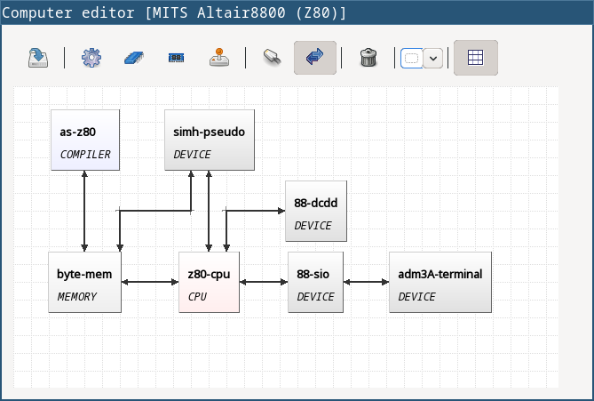
Computer schema
Computer schema represents a real configuration of the emulated computer. They are “drawn” in a computer schema editor. Users pick plugins that appear as “boxes” or elements on the screen. Then using connection lines those elements can be connected together to express a relation (that they can “see” each other).
Description of the control panel follows.
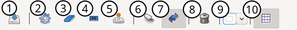
| 1 | Save the virtual computer. |
| 2 | Select a compiler. |
| 3 | Select a CPU. |
| 4 | Select a memory. |
| 5 | Select a device. |
| 6 | Use a connection line. The line is bidirectional by default. |
| 7 | Set or unset the connection line to be bidirectional. If the line is not bidirectional, the source direction is the first clicked element and the target direction is the second clicked element. |
| 8 | Remove an element from the schema. |
| 9 | This drop-down list is used for selecting a specific plugin (element) in the computer schema. See icons 2, 3, 4, and 5. The names are actually plugin JAR file names. |
| 10 | Use / do not use a grid in the editor. Elements are “snapped” to the grid if it is used, and it’s easier to draw the schema which looks good. The slider on the right then controls the density of the grid. The density is saved in the configuration file of the edited computer. |
Virtual computers in emuStudio are following the von-Neumann model of computers. It means that each computer must have a CPU and memory. Optionally one or more devices, and optionally a compiler.
Connection lines
The connection line represents a virtual “connection” between computer components. For the computer schema, it’s not important how the connection is realized. It’s safe to say that the connection is similar as if we say that a component “sees” the other component, in the direction of the arrow:
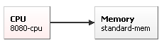
In the previous image, a CPU “sees” the memory, but not vice-versa. It means, CPU can read/write from/to memory, but memory is not seeing it, it can just answer to CPU requests. This connection makes sense in real-world computers.
Drawing connection lines is very easy. The connection line always connects exactly two elements in the schema. At first, the user must click on an already existing element in the schema. It’s just a click, not a drag.
Then a grey temporary line is being drawn having its end at the mouse position and moving with the mouse move. If the element is not really close, the user can make a “path” by clicking somewhere in the schema. At those locations, fixed-points are created.
When a user clicks at the second element, the temporary line disappears, and a real connection line is created.
The user can find the fixed-points later and move them by dragging. They can be removed by clicking at them with the right mouse button.