Operating memory “byte-mem”
This plugin emulates an operating memory with various features. It can be used for any virtual computer which can benefit from the following basic properties:
- A memory cell has a size of 1 byte (8 bits)
- Memory cells are linearly ordered (sequential)
- Each memory cell is accessible by a unique address, representing the index of the memory cell if the memory is imagined as an array of cells
Besides, the memory supports these additional features:
- Setting up ROM (read-only memory) ranges
- Changing memory size; by default it is 64kB
- Support of bank switching
There are also some “interactive” features:
- Manual loading/saving memory images in either binary or Intel HEX format
- Ability to automatically load a memory image at startup
- Intuitive control using keystrokes, and nice visual presentation of the data
This operating memory is (for now) used only in an 8-bit emulator of MITS Altair8800. However, it is possible to develop an emulator that can benefit from it.
GUI overview
To open the memory GUI (graphical user interface), click at the right-most icon in the debug toolbar, on the Emulator panel. The window is shown, as in the following image:
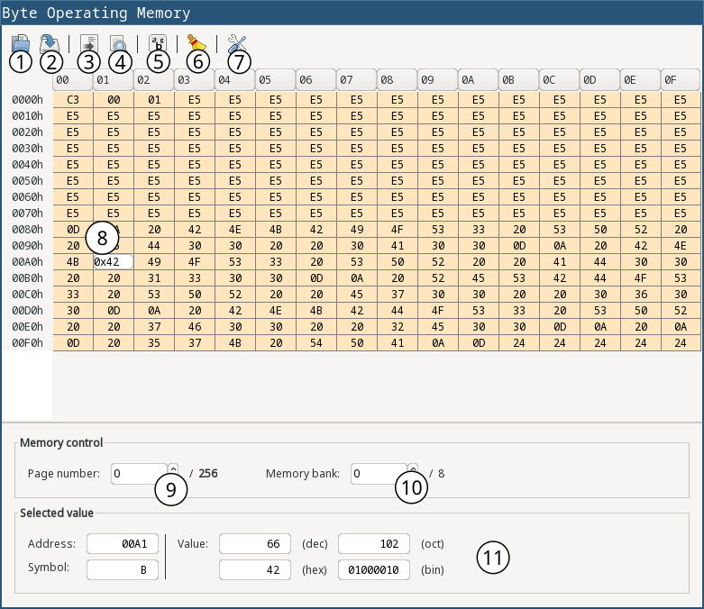
| 1 | Open a memory image. Current memory content which does not overlap with the loaded data will be kept. |
| 2 | Dump (save) whole memory content into a file. |
| 3 | Go to address. The address can be either in decimal, hexadecimal (prefix 0x) or octal (prefix 0) format. |
| 4 | Find a sequence. A dialog shows up where user can find either a plain text or sequence of bytes in the memory. |
| 5 | Toggle ASCII mode (ASCII mode means to render characters instead of character codes) |
| 6 | Erases all memory content. |
| 7 | Shows memory settings |
| 8 | By double-clicking on a memory cell it is possible to edit it and change its value. The value can be either in decimal, hexadecimal (prefix 0x) or octal (prefix 0) format. |
| 9 | Page of the memory view. The whole memory cannot be shown in single window, because it can be quite large, so it is split into pages. This split is just visual. |
| 10 | If the memory has set up memory banks, it is possible to change the view to different bank. Switching in here has no effect on the emulator and on the active bank. |
| 11 | Displays the data of the selected cell in various formats. |
Generally, it is possible to move around the cells using keystrokes (arrows). If the user presses some other letter/number key, a small text field appears allowing to edit the current value. When editing is finished, the user can press ENTER key to confirm it, or ESC key to discard the editing.
Memory settings
Settings window can be opened by clicking on “settings” icon in the main GUI window:
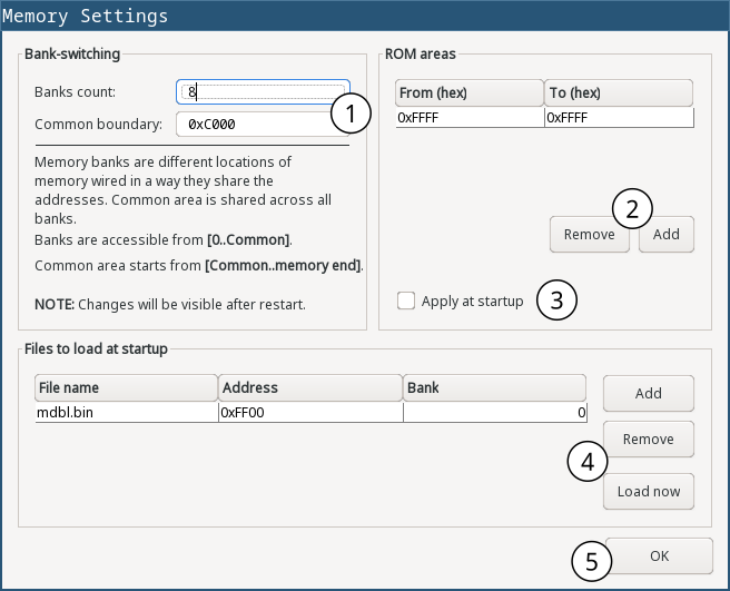
| 1 | Settings for memory bank-switching |
| 2 | Settings for ROM areas |
| 3 | If checked, settings for ROM areas will be saved to the configuration file |
| 4 | List of memory images which will be loaded at startup |
| 5 | The button will save and apply the settings |
ROM areas
Some computers or modern “controllers” organize memory into logical areas, some of which could be physically mapped to a read-only memory loaded with a firmware, or a game (e.g. in a “cartridge”). These memories are wired to specific addresses, so the programmer can access them as if they were part of operating memory.
The byte-mem plugin emulates this behavior. It allows to define ROM areas that represent read-only memory. There can be set up multiple ROM areas, and they can overlap. Effectively it means that memory cells in the ROM area cannot be changed from software running on the emulator. All writes to the memory will be ignored.
Manually, as a user, it is possible to change the values, but only by loading a new memory image. Editing a value will not work.
If a ROM range is defined, it is possible to “remove” only a part of it, effectively splitting the range and correcting their boundaries. For example, if there is defined a ROM range from 0x0A - 0x64, then it is possible to remove a range e.g. 0x32 - 0x46, which is the part of defined ROM area. Then, the original ROM area is split into two parts - first will be a range from 0x0A - 0x31, and the second from 0x47 - 0x64.
Memory bank-switching
This technique was invented as a workaround for a problem when the address space of a processor was smaller than memory size. To overcome this issue, memory was logically split into many regions of size equal to the processor address space. These regions are called “banks”.
Physically, banks could refer to the same memory, but they could be also different storages (e.g. external cartridges), and the bank-switching involved switching the active memory.
Selecting a bank from a programming perspective was usually done by writing some code to some I/O port using some I/O instruction of a CPU (controlled by a specialized chip). But it can be implemented in various ways, e.g. some memory addresses can be used for selecting a bank.
Also, it was very common that some part of the address space still kept some common memory part which was never switched out. This part is called a “common” part. In emuStudio, common part starts with the Common address (as it can be seen in the Settings dialog image above) and ends till the rest of the CPU address space (or memory end).
To summarize, let’s consider an example. If a CPU is 8-bit, it means it has address space of size 2^8 - i.e. it can access memory from address 0 to (2^8 - 1). If the memory was larger, CPU just doesn’t allow to access higher memory cells. So memory bank-switching is coming for the rescue. If the memory has 2 MB, we require 2^log2(2MB) = 2^21 addresses. So, if we won’t have any common address space, we require ceil(21 / 8) = 3 banks:
- bank 0: maps from 0 - (2^8 - 1)
- bank 1: maps from 2^8 - (2^16 - 1)
- bank 2: maps from 2^16 - (2^21 - 1)
Configuration file
The following table shows all the possible settings of byte-mem plugin:
| Name | Default value | Valid values | Description |
|---|---|---|---|
banksCount | 0 | >= 0 | Number of memory banks |
commonBoundary | 0 | >= 0 and < mem size | Address from which the banks are shared |
memorySize | 65536 | > 0 | Memory size in bytes |
ROMfrom(i) | N/A | >= 0 and < mem size | Start of the i-th ROM area |
ROMto(i) | N/A | >= ROMfrom(i) and < mem size | End of the i-th ROM area |
imageName(i) | N/A | file path | The i-th memory image file name. If it ends with .hex suffix, it will be loaded as Intel HEX format, otherwise as binary |
imageAddress(i) | N/A | >= 0 and < mem size | The i-th memory image load address |
Using memory in custom computers
This section is for developers of emulators. If you do not plan to create custom virtual computers, you can safely skip this section. To get started with developing plugins for emuStudio, please read developer documentation.
As it was mentioned in the earlier sections, the byte-mem plugin can be used in other computers, too. Besides standard operations which are provided by net.emustudio.emulib.plugins.memory.MemoryContext interface, it provides custom context API, enabling to use more features - e.g. bank-switching.
You can obtain the context in Plugin.initialize() method. The context is named net.emustudio.plugins.memory.bytemem.api.ByteMemoryContext:
...

public void initialize(SettingsManager settings){
        ByteMemoryContext mem=contextPoolImpl.getMemoryContext(pluginID,ByteMemoryContext.class);
        ...
        }
The memory context has the following content:
package net.emustudio.plugins.memory.bytemem.api;

import net.emustudio.emulib.plugins.annotations.PluginContext;
import net.emustudio.emulib.plugins.memory.MemoryContext;

import java.util.List;

/**
 * "Byte" memory context.
 * <p>
 * Supports bank switching, ROM ranges, and loading HEX/BIN files.
 */
@SuppressWarnings("unused")
@PluginContext(id = "Byte memory")
public interface ByteMemoryContext extends MemoryContext<Byte> {

    /**
     * Determine whether specified memory position is read-only.
     *
     * @param address memory position
     * @return true if the memory position is read only, false otherwise
     */
    boolean isReadOnly(int address);

    /**
     * Get list of ranges of read-only addresses.
     *
     * @return list of ROM memory addresses
     */
    List<? extends AddressRange> getReadOnly();

    /**
     * Set specified memory range as ROM (Read Only Memory).
     *
     * @param range address range
     */
    void setReadOnly(AddressRange range);

    /**
     * Set specified memory range as RAM (Random Access Memory).
     *
     * @param range address range
     */
    void setReadWrite(AddressRange range);

    /**
     * Get number of available memory banks.
     *
     * @return count of memory banks
     */
    int getBanksCount();

    /**
     * Get index of the selected memory bank.
     *
     * @return index of active (selected) memory bank
     */
    int getSelectedBank();

    /**
     * Select (set as active) a memory bank.
     *
     * @param bankIndex index (number) of a bank which should be selected
     */
    void selectBank(int bankIndex);

    /**
     * Return an address in the memory which represents a boundary from which
     * the memory banks have the same content. Before this address all banks
     * can have different content.
     *
     * @return common boundary address
     */
    int getCommonBoundary();

    /**
     * Returns raw memory represented by Java array.
     * <p>
     * Memory notifications must be handled manually if this array changes.
     *
     * @return raw memory
     */
    Byte[][] getRawMemory();

    /**
     * This interface represents a range of addresses in the memory.
     */
    interface AddressRange {
        int getStartAddress();

        int getStopAddress();
    }
}