Serial board 88-SIO
Altair 8800 computer was equipped with serial board called 88-SIO, or 88-2SIO. It was a device which allowed connecting other devices using RS-232 interface. From one side it was attached to CPU on at least two ports (most commonly 0x10 and 0x11 for terminal). The other side ended with one physical port allowing to connect one device. A variant called 88-2SIO allowed to connect two devices at the same time.
Usually, attached devices were:
- serial terminal
- line printer
- paper tape reader/punch
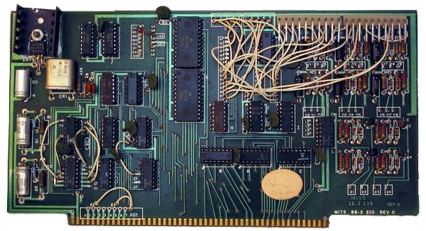
The following image shows MITS 88-2SIO board.
Original manual of MITS 88-SIO serial board can be found here, here or here.
Features
The plugin emulates only basic functionality of the board (e.g. it does not emulate transfer rate). It has the following features:
- allows to connect one device
- CPU ports are configurable
- supports input/output interrupts
- has a GUI
GUI can be seen here:
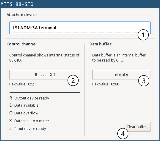
The window shows attached device, control channel and data buffer.
| 1 | Attached device name |
| 2 | Control channel status. Control channel is used to retrieve 88-sio status, or enable/disable interrupts. The displayed value shows the status. For details see the 88-sio manual. |
| 3 | 88-sio has internal buffer used for caching one byte coming from the connected device. If the CPU is not fast enough to read it, the data can be overwritten by new data coming from the device. However, the buffer is not used when sending data to the connected device from CPU. Thus writing data from CPU won’t clear data coming from device. |
| 4 | Clear internal data buffer |
Settings
88-sio plugin has a separate settings window with three sections, described below.
General settings
The 88-sio plugin support various behaviors of the data transfer, which in reality was the behavior of connected devices and not 88-sio. The reason for supporting these features here is to allow some versatility, regardless of which device is connected. These general settings can be seen in the Settings window:
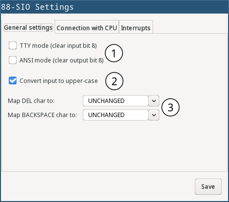
| 1 | TTY/ANSI mode. On TTY mode, clears input bit 8 (performs AND 0x7F on the byte coming from device). On ANSI mode, clears output bit 8 (performs AND 0x7F on the byte coming from CPU). |
| 2 | Converts input data to upper-case (the byte coming from device). |
| 3 | Maps input/output data Backspace or Delete character to some other character. Possibilities are: Backspace, Delete, Unchanged. |
CPU Ports settings
MITS 88-SIO board in emuStudio is attached to CPU through several ports. In order to support various Altair8800 configurations and thus using wider variety of original software, the device control and data channels are connected to multiple CPU ports. This makes effectively an impression as if there existed multiple 88-sio cards connected to the same device.
By default, used CPU port allocation is:
- Control channel (or “status port”):
0x10,0x14,0x16,0x18(most commonly used:0x10for terminal) - Data channel (or “data port”):
0x11,0x15,0x17,0x19(most commonly used:0x11for terminal)
A side note: there existed various additional boards which supported RS-232 communication besides 88-SIO (or 88-2SIO). These boards were compatible with S100 system board, thus they were usable for original Altair8800 computers as well as its clones. For example: CompuPro Support Board (status port 0x5C, data port 0x5D), CompuPro Interfacer (manual here, consuming 8 CPU ports), Cromemco TU-ART board, IMS C00480 4-line board, IMS I/O board, IMSAI SIO Board, Intersystems 6-SIO, etc.
But back to 88-sio. The port numbers allocation can be changed in the Settings window:
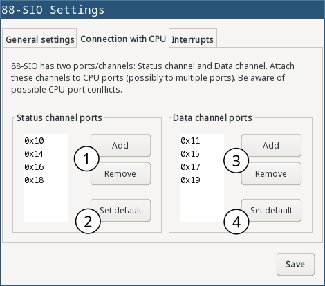
| 1 | Attach/detach control channel (“status port”) to/from CPU port |
| 2 | Reset control channel CPU ports to default ones (0x10, 0x14, 0x16, 0x18) |
| 3 | Attach/detach data channel (“data port”) to/from CPU port |
| 4 | Reset data channel CPU ports to default ones (0x11, 0x15, 0x17, 0x19) |
Interrupts settings
88-sio supports input and output interrupts. If enabled, input interrupt is signalled to CPU when a data becomes available from the connected device. An output interrupt is signalled when data is sent to device. Interrupts support can be generally enabled or disabled, along with interrupt vector configuration in Settings window:
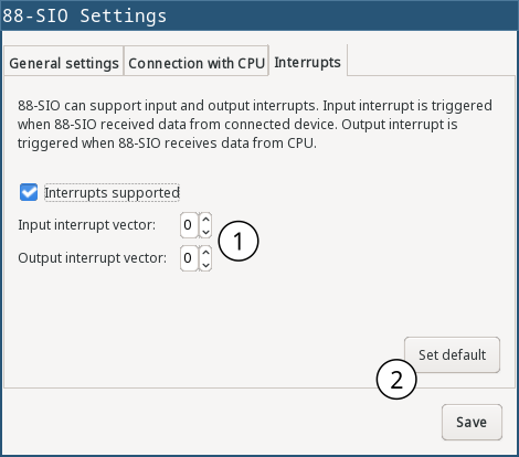
| 1 | Enable/disable interrupt support and set interrupt vectors. If interrupts are disabled, they cannot be enabled in software (see “Port 1” section below). |
| 2 | Reset to default. Interrupts will be supported and interrupt vector is set to 7 (equivalent to calling RST 7 instruction) |
Configuration file
The following table shows all the possible settings of MITS 88-SIO plugin:
| Name | Default value | Valid values | Description |
|---|---|---|---|
statusPorts | "0x10, 0x14, 0x16, 0x18" | > 0 and < 256; X range from 0 upwards | CPU-ports mapped to status port of 88-sio |
dataPorts | "0x11, 0x15, 0x17, 0x19" | > 0 and < 256; X range from 0 upwards | CPU-ports mapped to data port of 88-sio |
clearInputBit8 | false | true/false | Whether to clear 8th bit of the input written to 88-sio |
clearOutputBit8 | false | true/false | Whether to clear 8th bit of the output, read from 88-sio |
inputToUpperCase | false | true/false | Whether to convert the input written to 88-sio into upper-case |
mapDeleteChar | "UNCHANGED" | BACKSPACE, DELETE, UNDERSCORE, UNCHANGED | Maps a “DEL” input key/character to given value. For example, if user presses “DEL” the 88-sio can map it as if user pressed “BACKSPACE”. |
mapBackspaceChar | "UNCHANGED" | BACKSPACE, DELETE, UNDERSCORE, UNCHANGED | Maps a “BACKSPACE” input key/character to given value. For example, if user presses “BACKSPACE” the 88-sio can map it as if user pressed “DEL”. |
interruptsSupported | true | true/false | Whether interrupts are supported in general. When disabled, they cannot be enabled in software. |
inputInterruptVector | 7 | 0-7 | Set input interrupt vector. 88-sio will signal an interrupt to the CPU as RST instruction on the input (e.g. a key press) if input interrupts are enabled |
outputInterruptVector | 7 | 0-7 | Set output interrupt vector. 88-sio will signal an interrupt to the CPU as RST instruction on the output (e.g. on displaying a char) if output interrupts are enabled |
Programming
In order to show something useful, let’s assume that a terminal LSI ADM-3A is attached to the board. Remember, the board only mediates the communication, it does not interpret any of the sent/received characters.
CPU Ports
Whole communication between the board (and attached device) and CPU is controlled by programming the two ports: Status port and Data port. The following table shows the ports and how they are used.
| Channel | Address | Input | Output |
|---|---|---|---|
| Control (port 1) | 0x10, 0x14, 0x16, 0x18 | Read board status | Used for enabling/disabling input/output interrupts. |
| Data (port 2) | 0x11, 0x15, 0x17, 0x19 | Read data | Write data |
Now, detailed description of the ports follow. Bits are ordered in a byte as follows:
D7 D6 D5 D4 D3 D2 D1 D0
where D7 is the most significant bit, and D0 the least significant bit.
Control channel (port 1)
WRITE:
Controls input/output interrupts enable.
D7 D6 D5 D4 D3 D2: unused bitsD1: Enable/disable output interrupts (0 - disable, 1 - enable)D0: Enable/disable input interrupts (0 - disable, 1 - enable)
Interrupts (both input and output) are signalled to the CPU as RST instruction with the interrupt vector value used from the 88-SIO plugin settings (by default, RST 7 is signalled).
Input interrupt is triggered when a device connected to 88-SIO sends data to it, so CPU will be notified to read it. Output interrupt is triggered when CPU sends data to 88-SIO, which effectively calls CPU again.
READ:
Read status of the device.
D7: Output device ready. Always 0 in the emulator.D6: Not used (always 0).D5: Data available (for writing to the attached device). Always 0 in the emulator, meaning that no data is pending to be written. Data are written immediately afterOUTinstruction.D4: Data overflow. Value 1 means a new word of data has been received before the previous word was inputted to the accumulator. In emuStudio, this never happens.D3: Framing error. Value 1 means that data bit has no valid stop bit. In emuStudio, this never happens.D2: Parity error. Value 1 means that received parity does not agree with selected parity. In emuStudio, this never happens.D1: Transmitter buffer empty. Value 1 means that the data word has been received from the attached device and it’s available for reading (from the Data port).D0: Input device ready. Value 1 means that the CPU can write data to the SIO (that the board is ready). Always 1 in the emulator.
Data channel (port 2)
WRITE:
Write data to the attached device.
READ:
Read data from the attached device.
If the attached device sends asynchronously multiple data, the emulated board stores all in a buffer (queue) with unlimited capacity, so no data should be lost and can be read anytime.
Program example
In this section it will be shown a small “How to” program terminal using 88-SIO ports.
Print a character on screen
In emuStudio, it is enough to write data to Port 2, e.g.:
mvi a, 'H'
out 11h
mvi a, 'i'
out 11h
Print a string on screen
For writing strings, it is more practical to have a procedure.
lxi h, text  ; load address of 'text' label to HL
call print   ; print text
hlt          ; halt CPU

text: db 'Hello, world!',0

; Procedure for printing text to terminal.
; Input: pair HL must contain the address of the ASCIIZ string
print:
    mov a, m  ; load character from HL
    inx h     ; increment HL
    cpi 0     ; is the character = 0?
    rz        ; yes; quit
    out 11h   ; otherwise; show it
    jmp print ; and repeat from the beginning
Reading character from keyboard
For reading a character, it is required to read the Port 1 until the character is not ready. Then we can read it from Port 2.
; Procedure will read a single character from terminal
; Input: none
; Output: register A will contain the character.
getchar:
    in 10h     ; read Port 1
    ani 1      ; is data ready ?
    jz getchar ; not; try again
    in 11h     ; yes; read it (into A register)
    ret
Reading text from keyboard
Now follows an example, which will read a whole line of characters into memory starting at address in DE pair. The procedure will interpret some control keys, like: backspace and ENTER keys.
lxi h, text        ; load address of 'text' label to HL
xchg               ; DE <-> HL
call getline       ; read line from the keyboard into DE

lxi h, text        ; load 'text' address again
call print         ; print the text on screen

hlt                ; halt CPU

text: ds 30        ; here will be stored the read text

;Procedure for reading a text from keyboard.
;Input: DE = address, where the text should be put after reading
;       C  = is used internally
getline:
    mvi c, 0       ; register C will be used as a counter of
                   ; read characters
next_char:
    in 10h         ; read Port 1: status
    ani 1          ; is the char ready for reading?
    jz next_char   ; not; try again
    in 11h         ; yes; read it to A register

    ; now ENTER and Backspace will be interpreted
    cpi 13         ; ENTER?
    jz getline_ret ; yes; it means end of input
    cpi 8          ; Backspace ?
    jnz save_char  ; if not; store the character

    ; Backspace interpretation
    mov a, c       ; A <- number of read characters
    cpi 0          ; are we at the beginning?
    jz next_char   ; yes; ignore the backspace

    dcx d          ; not; decrement DE
    dcr c          ; decrement count of read characters
    mvi a,8        ; "show" the backspace (terminal will
                   ; interpret this by moving the cursor
                   ; to the left by 1 char)
    out 11h
    mvi a, 32      ; "clear" the current character on screen
                   ; by a space character (ASCII code 32)
    out 11h

    mvi a,8        ; and move the cursor back again
    out 11h
    jmp next_char  ; jump to next char

save_char:         ; stores a character into memory at DE
    out 11h        ; show the character in A register
    stax d         ; store it at address DE
    inx d          ; increment DE
    inr c          ; increment number of read characters
    jmp next_char  ; jump to next char

getline_ret:       ; end of input
                   ; ENTER will be stored as CRLF
    mvi a,13       ; CR (Carriage Return)
    stax d         ; store the char
    inx d          ; increment DE
    mvi a, 10      ; LF (Line Feed)
    stax d         ; store the char
    inx d          ; increment DE
    mvi a, 0       ; char 0 (End-Of-Input)
    stax d         ; store the char
    ret            ; return
Get notified when a key is pressed
In this example, an interrupt is signalled when user presses a key on keyboard.
; Tests signalling interrupts on input
mvi a, 1      ; 88-SIO: input interrupts enable
out 0x10

ei            ; enable CPU interrupts
loop:
jmp loop      ; do this forever (or until...)

; interrupt handler
org 0x38      ; assuming interrupt vector is set to 7
in 0x11       ; read char from 88-SIO (and ignore it)
lxi h, key    ; load address of 'key' label to HL
call print    ; print "key pressed"
ret           ; return from the interrupt

key: db 'Key pressed!',10,13,0

; Procedure for printing text to terminal.
; Input: pair HL must contain the address of the ASCIIZ string
print:
    mov a, m  ; load character from HL
    inx h     ; increment HL
    cpi 0     ; is the character = 0?
    rz        ; yes; quit
    out 11h   ; otherwise; show it
    jmp print ; and repeat from the beginning